ESP32-PICO-KIT V4 Getting Started Guide
This user guide shows how to get started with the ESP32-PICO-KIT V4 mini development board. For description of other versions of the ESP32-PICO-KIT check ESP32 Hardware Reference.
What You Need
- 1 × ESP32-PICO-KIT V4 mini development board
- 1 × USB A / Micro USB B cable
- 1 × PC loaded with Windows, Linux or Mac OS
Overview
ESP32-PICO-KIT V4 is a mini development board based on the ESP32-PICO-D4 SIP module produced by Espressif. For easy interfacing, all the IO signals and system power on ESP32-PICO-D4 are led out through two 20 x 0.1” pitch header pads on both sides of the development board. To make the ESP32-PICO-KIT V4 fit into mini breadboards, the header pads are populated with two 17 pin headers. Remaining 2 x 3 pads grouped on one side of the board besides the antenna are not populated. If required, the additional 2 x 3 pin headers may be soldered later by the user. The development board integrates a USB-UART Bridge circuit, allowing the developers to connect the board to a PC’s USB port for downloads and debugging.
Note
The 2 x 3 pads not populated with pin headers are internally connected to the flash memory embedded in the ESP32-PICO-D4 SIP module. For more details see module’s datasheet in Related Documents.
Functional Description
The following list and figure below describe key components, interfaces and controls of ESP32-PICO-KIT V4 board.
- ESP32-PICO-D4
- Standard ESP32-PICO-D4 module soldered to the ESP32-PICO-KIT V4 board. The complete system of the ESP32 chip has been integrated into the SIP module, requiring only external antenna with LC matching network, decoupling capacitors and pull-up resistors for EN signals to function properly.
- USB-UART Bridge
- A single chip USB-UART bridge provides up to 1 Mbps transfers rates.
- I/O
- All the pins on ESP32-PICO-D4 are broken out to the pin headers on the board. Users can program ESP32 to enable multiple functions such as PWM, ADC, DAC, I2C, I2S, SPI, etc.
- Micro USB Port
- USB interface. It functions as the power supply for the board and the communication interface between PC and ESP32-PICO-KIT V4.
- EN Button
- Reset button; pressing this button resets the system.
- BOOT Button
- Holding down the Boot button and pressing the EN button initiates the firmware download mode. Then user can download firmware through the serial port.
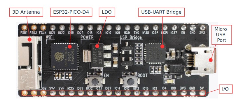
ESP32-PICO-KIT V4 board layout
Power Supply Options
There following options are available to provide power supply to the ESP32-PICO-KIT V4:
- Micro USB port, this is default power supply connection
- 5V / GND header pins
- 3V3 / GND header pins
Warning
Above options are mutually exclusive, i.e. the power supply may be provided using only one of the above options. Attempt to power the board using more than one connection at a time may damage the board and/or the power supply source.
Start Application Development
Before powering up the ESP32-PICO-KIT V4, please make sure that the board has been received in good condition with no obvious signs of damage.
To start development of applications, proceed to section Get Started, that will walk you through the following steps:
- Setup Toolchain in your PC to develop applications for ESP32 in C language
- Connect the module to the PC and verify if it is accessible
- Build and Flash an example application to the ESP32
- Monitor instantly what the application is doing